ESP32 and CAD with Claude Code
6 min read
I wanted to see if Claude Code would be able to do a good job at microcontroller code and creating an enclosure for a not super popular ESP32 (M5Stack M5Dial) board I bought on sale a while ago. link to github repo
ESP32 NTP Server
The premise is that one of my hobbies is using ham radio digital modes like FT8 and JS8Call. Those modes operate on transmit and receive cycles and so you need to have an accurate time on your machine (docs say 1-2 seconds is usually fine). Otherwise, you may transmit or receive at the wrong time and not decode messages properly. Sure, I could just use a cheap USB GPS adapter with gpsd or I could even use the GPS that is built into the 4G modem in my old Toughbook CF-C2 (link to repo about that), but where's the fun in that? I also kept forgetting how to setup the GPS as a proper time source (my old scripts are only for the Toughbook modem, not for the USB GPS modules). For my use case, its fine to boot up my portable WiFi router and portable NTP server and then just hit my Linux machine with a quick ntpdate. If i want to be real paranoid I could do that every 30-60 minutes but I can't imagine RTC circuits in laptops or mini-pcs being so terrible as to drift seconds in an hour.
Getting Claude to create the NTP server wasn't anything too special, just a few prompts and back and forth as usual. But I found in the M5Stack docs something about being able to power off and on the device with a button but it didn't really say if it was the reset button or if it was the button that was under rotary encoder.
Understanding Schematics
So I asked if it was possible to power off and on the device and in the thoughts there was something like "if you provide schematics then I can figure how to use the power button". I couldn't really find any examples of people doing this but the TUI just let me drag and drop the two page PDF schematic and Claude was able to figure out how to use the on/off functionality and properly explain how it worked.
While I was testing the power off/on, I had a USB current meter in line with the USB cable for programming/power and I found that the ESP32 didn't fully turn off as there was still ~100mA of current draw and the power LED for the GPS was on. I complained to Claude about this and based on the schematics and information about ESP32s, the reply was something about how the USB being connected caused the power rails to not actually turn off so that programming can work correctly. And sure enough that was the case, when I connected the micro JST connector the M5Dial to my variable PSU, I saw that there was 0 current draw when the ESP32 was powered off via software. And the rotary encoder button was able to power on the device without issue.
I may have been able to sit there and read the board schematics but I probably would have given up and gone with the low tech approach of putting a power switch in line with the battery so that I could be 100% certain the battery was not being used when things were off.
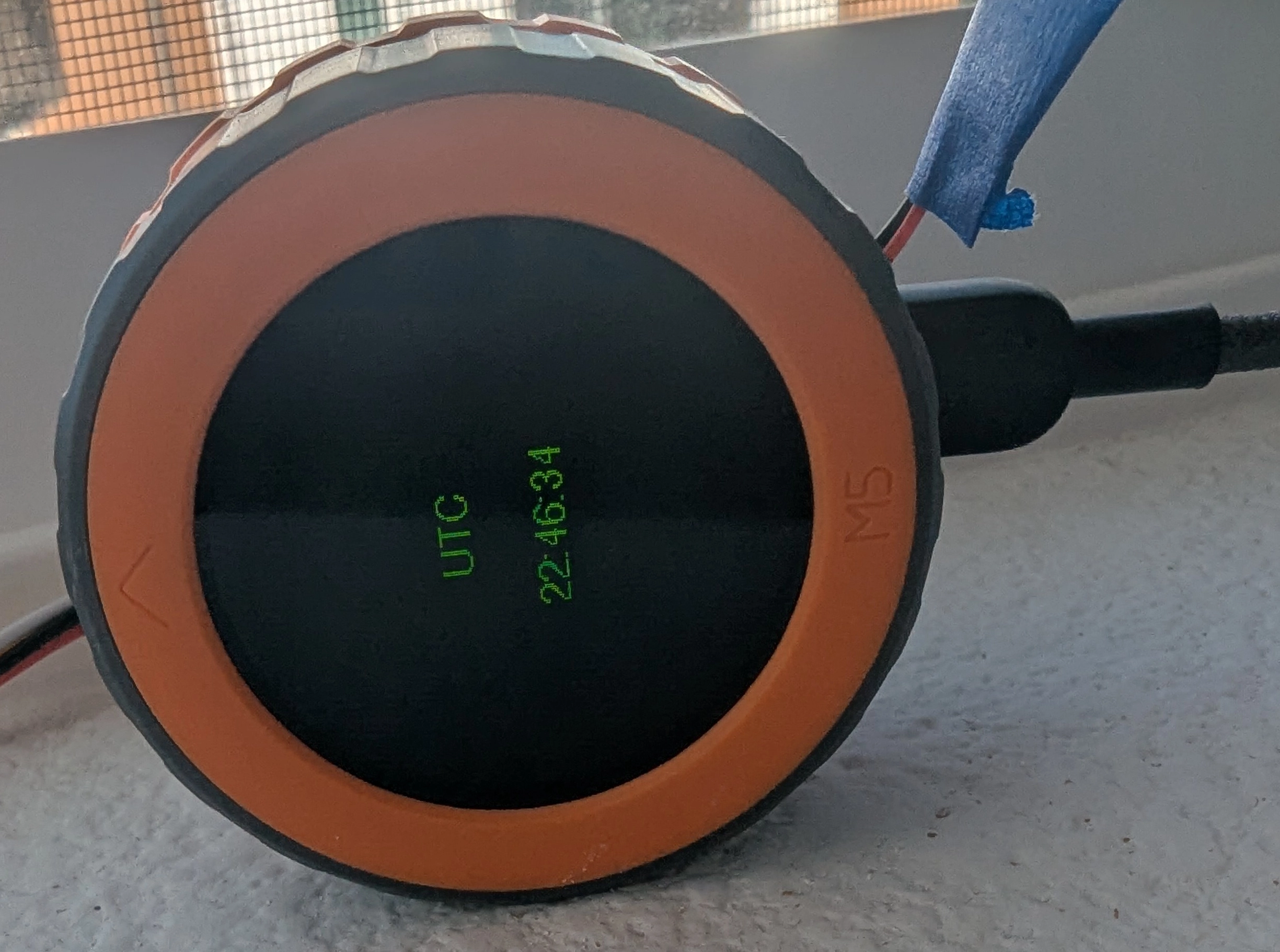
The M5Stack libraries don't really have much documentation nor examples but the other cool part about Claude Code is that it will use the sed command (to grab specific parts of files) to go and try to understand how to use the available libraries. And along with the file upload, it was also effective to take pictures of the M5Dial screen to ask things like "can you use the picture as a reference to better fill up the screen with the current time?"
 Otherwise I was generally impressed by the generated code and how it compiled and uploaded without issue on each iteration.
OpenSCAD Enclosure
I'm not amazing at CAD, I have gotten much better at using Onshape in the last year or so but it feels like such a pain to go and put in all the measurements and then do extrusions in specific faces and such. I had briefly tried OpenSCAD a while ago but I had trouble getting into it. For fun I tried getting Claude to create the enclosure for me.
I put together this basic sketch and some extra details and after one of the Claude "interviews" I was able to get a pretty good result on the first pass.
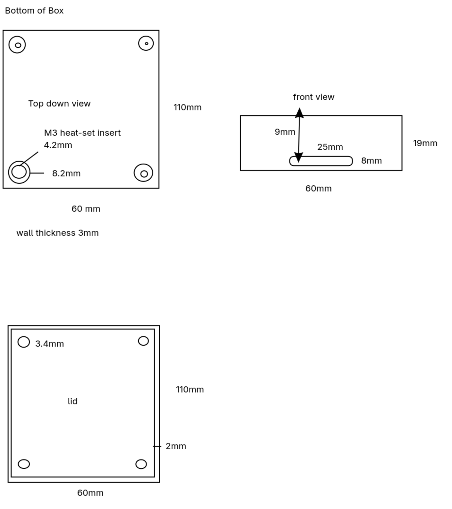 I found it helpful to give a reason behind each cutout, for example I said something like "on the lid, 4mm from the front edge, create a hole 44mm in diameter for the M5Dial". The result is comments around the generated OpenSCAD code for that part of the model which is real helpful to come back to, since I could just start a new session and say "in box.scad, put a chamfer around the USB type-c port so that most cables can fit and dust ingress is reduced".
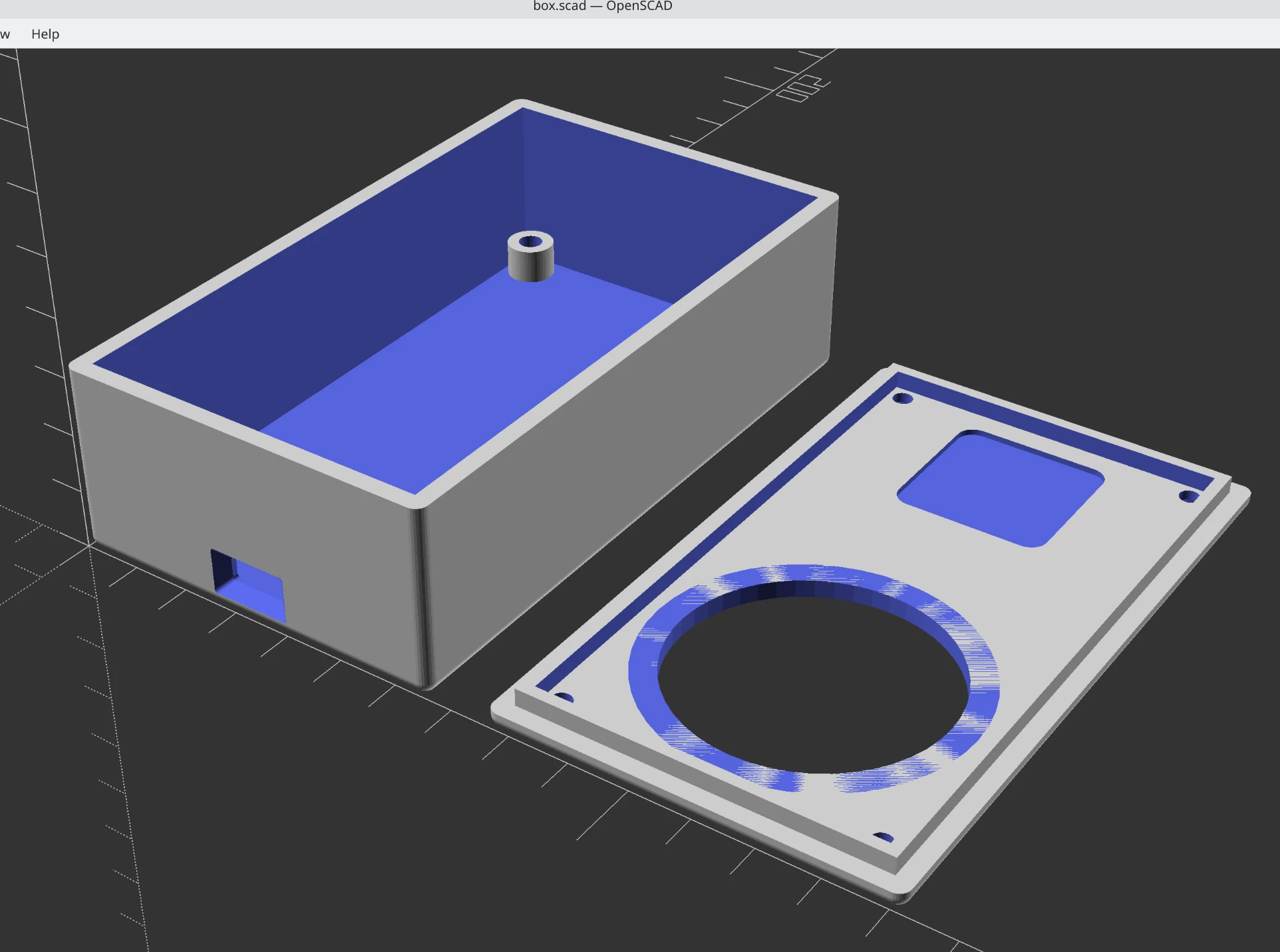
In one way, it not super surprising that Claude can work on OpenSCAD because it is basically just programming but the code generates one or more 3D parts.
Physical Build Pictures
My soldering and spacial planning skills still have much to be desired but I did manage to squeeze in everything into a relatively small box and it seems to be fairly secure.
It's really hard to find USB type-c panel mounts. The only ones I found had really large plugs because they were all USB 3.1/10gbps which I really didn't need for my USB 2.0 use case. I ended up using a cheap type-c breakout board that has the 5.1k ohm resistors on the CC lines for most type-c cables and charging bricks to work.
I struggled to scavenge a USB type-a to type-c that had data lines, as many of the cheap charging cables only have the 5V and GND lines connected to save a few cents. I found one and hacked off the type-a side and soldered that to some wires and then to the breakout board. Used a USB testing board to make sure I probably won't let out the magic smoke.
Also, the M5Dial has a JST battery connector which has red for negative and black for positive so I got to solder a two unfinished JST connectors backwards to each other.


And finally, the finished product

NTP Results
Before doing this, I ran sudo ntpdate time.nist.gov.
About 30 minutes before this, I got the time from GPS and then shut off the device.
Result from the RTC without a GPS lock:
ntpdate -q esp32-ntpserv; ntpdate -q time.nist.gov
2026-03-24 23:00:34.691000 (-0700) -1.112715 +/- 1.007431 esp32-ntpserv 192.168.2.107 s2 no-leap
2026-03-24 23:00:35.929655 (-0700) -0.000599 +/- 0.023473 time.nist.gov 132.163.97.4 s1 no-leap
And when there’s a GPS lock its pretty decent:
ntpdate -q esp32-ntpserv; ntpdate -q time.nist.gov
2026-03-24 23:13:09.364999 (-0700) -0.182772 +/- 0.068339 esp32-ntpserv 192.168.2.107 s1 no-leap
2026-03-24 23:13:09.762481 (-0700) +0.000746 +/- 0.024571 time.nist.gov 132.163.97.6 s1 no-leap
update: I also did this later the next day to see if there was more drift. I think I may try avoiding using the RTC time for the radio stuff, especially if its been too long since the last GPS fix. So at that point it would just be a decent clock.
2026-03-25 14:11:25.130000 (-0700) -2.796399 +/- 1.063500 esp32-ntpserv 192.168.2.107 s2 no-leap
2026-03-25 14:11:28.052117 (-0700) +0.001257 +/- 0.024032 time.nist.gov 132.163.96.6 s1 no-leap
If you want to try and do this yourself or steal the code for some other ESP32 board the OpenSCAD model and code is here in github repo. The code for the NTP server should be fairly easy to put on other ESP32 boards.
It uses about 1W of power when the screen is on so a 3000mAh battery theoretically gets you around 12 hours of runtime.